Volute casing are classified on the basis of Cross-section of Volute passage and splitting of outlet passage for blower.
PARALLEL SIDE WALLS
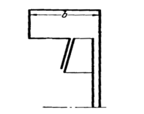
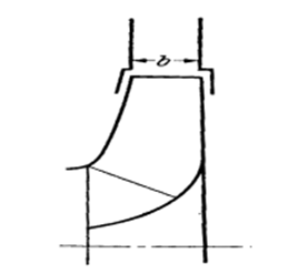
In this type of volute casing the sides of the casing are parallel as shown in figure: 1.1. The width of the casing is nearly kept equal to the width of the impeller. With most ventilation blowers this is the normal form of design. In this the width of casing is wider than the impeller width as shown in figure: 1.2.
RECTANGULAR CROSS SECTION
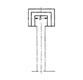
This type of volute casing has geometrically similar section as shown in figure: 1.3. The individual section whose basic shape is rectangular should be altered radially and axially so that it results in similar areas. These construction naturally yield no body of rotation with reference to the sidewalls, so that deviations from the law “r x Cq = constant” are to be expected.
TRAPEZOIDAL CROSS SECTION
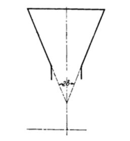
In this type of casing the two sides of casing are tapered which is obtained by an angle 2d between sides as shown in figure: 1.4 and is usually about 60°.The larger 2d results turbulence and inefficiency while smaller 2d increased casing diameter and weight of the inflatable air blower. The selection of delta is dependent upon separation of flow.
CIRCULAR CROSS SECTION
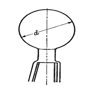
If the diameter‘d’ of the volute section is not too great in relation to the total casing diameter then the hyperbolic path over the circular section is very flat. In this type of volute one should first of all selects ‘d’ approximately, mean while one calculates the cross-section which gives a constant velocity ‘c’ in the complete volute. In this case, the section increases proportionally to the admission arc as shown in figure: 1.5.
INNER VOLUTE
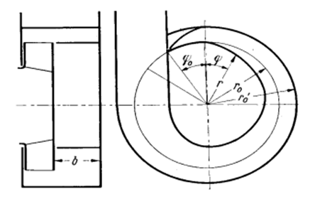
In this type of volute the air flows around the impeller and will be divided on one or both sides of impeller. According to the law of rotation the peripheral component will be subsequently larger. This gives rise to a significantly smaller volute as shown in figure: 1.6. The impeller friction falls off because the air flows along the disc with a larger velocity. The friction that in the volute is significantly shorter than in case of normal construction. On such type of casing the discharge velocity are high so that a diffuser must be fitted to the outlet.
AXIAL VOLUTE
This type of volute has the great advantage of arising from cylindrical surfaces. In this the “volute” is developed between two co-axial cylinders in the axial direction as shown in figure: 1.7. In order to achieve the outside diameter of the entry to the volute the air already divides before the tongue so that the volume which flows in at 0° goes through the complete casing. On account narrow rectangular section of these volutes essential losses arise through secondary flows.

HELIX VOLUTE
These types of volutes are especially suitable for axial flow fan in which the velocity behind the impeller is neither changed in magnitude nor in direction as shown in figure:1.8. In this the conversion of the high velocity of discharge into static pressure, and then carried out in a connected straight diffuser.
HELIX-FORMED CONSTRUCTION OF VOLUTE CASING
The volute casing is the best and simplest guide or diffusion arrangement for radial-flow fans which is known in fan engineering as shown in figure: 1.9. This is not so for axial-flow fans. This is all the more regrettable as the use of volute casing with axial flow fans, produces a large unit, and in addition to this numerous experiments have shown it can cause undue loses.

SUBDIVIDED VOLUTE CASING
With large radial extent of the volute casing undue disturbances arise through secondary streams. Depending upon circumstances, this influence can be modified if; one resolves an average tongue into two or more spirals. Such type of volute casing is also known as double volute casing as shown in figure: 1.11. In this type of volute casing radial thrust can be reduced considerably. If one requires decreasing the discharge velocity at the same time in the shortest possible space, then to get this one can subdivide the discharge section with a number of guide blades as shown in figure: 1.10.

For large volumes one can go a step further. By sub-division and partial profiling of the guide blades, air is discharged at a width which is more than double the diameter of impeller. It is used with impellers having high volume co-efficient, i.e. multivaned impellers.
VOLUTE CASING WITH AN ADJUSTABLE TONGUE
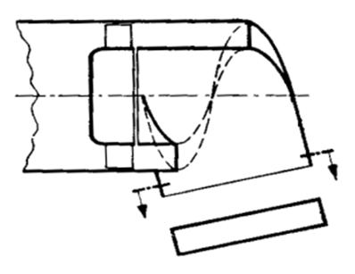
The requirements often demand that a volute casing must satisfy different volumes in order to avoid too large a loss when the duty falls below normal design conditions. Particularly in mine ventilation, for example, the conditions are continuously changing so that this aspect is extremely important. The adjustable tongue ends are available for different positions the effect of such measures is limited as shown in figure: 1.11.

Related Posts:
…a radial flow component (generally small) at the discharge.The impeller may be mounted in either a cylindrical or volute housing. (A volute is the outer casing that contains the spinning rotor in a centrifugal device.)…
Introduction of Different Sections of Blower
VOLUTE CASING The purpose of the blower casing is to guide the fluid from the impeller or diffuser and convert into pressure. The flow with high kinetic energy is discharge from impeller and leads gas or air away.
