Fan laws relate the performance characteristics of any geometrically similar series of fans. CFM, RPM, SP and HP are all related to each other in a known manner and when one changes, all others change. The CFM variable is the most commonly changed measurement in an air moving system therefore the following example of Fan Law application is based on a change from an existing CFM to a new CFM. The simplified form of the most commonly used fan laws include.
Cfmfinal=Cfminitial(RPMfinal/RPMinitial)
SPfinal=SPinitial(RPMfinal/RPMinitial)2
HPfinal=HPinitial(RPMfinal/RPMinitial)3
The laws governing fan operation provide a useful tool for determining requirements when changing the volume capacity of a fan is required for a given system. At a new fan rotational speed, the new operating point for a given fan can be determined from the fan laws.
Example:
A fan installed in a fixed system is operating at 10000 CFM @ 1.5”-wg, running 1000 RPM using 5 BHP. What RPM is required to move 25% more air (12500 CFM) through the system?
Solution
By rearranging the cfm fan law:
RPM2=(CFM2/CFM1)*RPM1
RPM2=(12,500/10,000)*1000=1250RPM
The corresponding static pressure is:
SP2=SP1(RPM2/RPM1)2
SP2=1.50(1250/1000)=2.34
The resulting BHP is:
BHP2=BHP1(RPM2/RPM1)3
BHP2=5.00(1250/1000)3=9.77BHP
According to the fan laws, in order to use the original fan, the speed must be increased from 1000 RPM to 1250 RPM; the motor must be changed from a 5 HP to 10 HP.
Figure below illustrates fan curves for both the original and new fan performance.

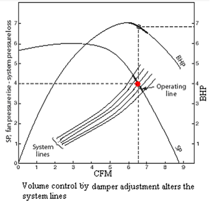
Note that these laws apply only when all flow conditions are similar. Increasing the speed of a fan causes changes in several important parameters, which may invalidate the fan laws. Sometimes a fan system does not operate properly according to the design conditions. The measured airflow in the fan system may be deficient or it may be delivering too much CFM. In either case, it is necessary to either speed the fan up or slow it down to attain design conditions. We can graphically present new SP curves and BHP curves under different control scenarios as shown below:


The fan control method is the means by which the fan/system operating point is manipulated in order to change the desired flow/pressure somewhere else in the system. If you change the system resistance, the operating point will move along the fan curve. Fans equipped with an outlet damper, opposed bladed inlet box damper or a system damper are examples. If you change the fan performance capability, the operating point will move along the established system resistance curve. By having the ability to adjust both the system and the fan performance, the operating point can be moved to almost any desired position under the centrifugal fan curve. Controls which move the operating point along the system curve include variable inlet vanes, parallel bladed inlet box dampers, blade angle changes on axial fans and the many techniques used to change fan speed. The speed changes represent an example of fan control that can be accomplished through drive changes or a variable speed motor. It is extremely important to know the individual performance characteristics for each type of centrifugal fan when working on efficient control strategies and/or energy conservation.
Related Posts:
The most commonly used fan characteristic is the relationship between pressure rise and volume flow rate for a constant impeller speed (RPM). The air movement has a pressure associated with it…
Performance Characteristics of a Blower
The actual shape of blower performance curves is determined by the combined effect of the hydraulic losses of the impeller and casing. Mechanical losses including disk friction remains the same for all capacities and…
