The most commonly used fan characteristic is the relationship between pressure rise and volume flow rate for a constant impeller speed (RPM). The air movement has a pressure associated with it, which is termed as static pressure (SP) and the velocity pressure (VP). The static pressure (SP) is the useful working pressure available for overcoming the resistance of a ventilating system and is exerted in all directions at once weather in motion or not. SP may be +ve or –ve. Velocity pressure (VP) is the pressure due to the speed of the air and is always +ve and exerted in direction of flow. The total pressure (TP) produced by a fan is made up of the static pressure (SP) and the velocity pressure. Fan pressure rise characteristics are normally expressed in either TP or SP, with static pressure being the unit most commonly used in the United States. The fan volume flow rate is commonly expressed in cubic feet per minute, or CFM. Therefore, the system pressure loss and volume flow rate requirements are typically expressed as a certain value of static pressure (SP) at some CFM. The fan “pressure-volume” curve is generated by connecting the fan to a laboratory test chamber in accordance with the very specific test procedures outlined in the Air Movement and Control Association (AMCA) Standard 210. The starting point is to measure the airflow at zero pressure, sometimes referred to as free inlet & discharge or FID. The test rig is then adjusted to increase the pressure that the fan has to work against and to measure the airflow at each point. Data points are collected and plotted graphically for a constant rpm, from a “no flow” block off condition to a “full flow” or wide condition. Figure below represents such a curve that is typical for a vaneaxial fan, and is commonly referred to as a “static pressure” curve.
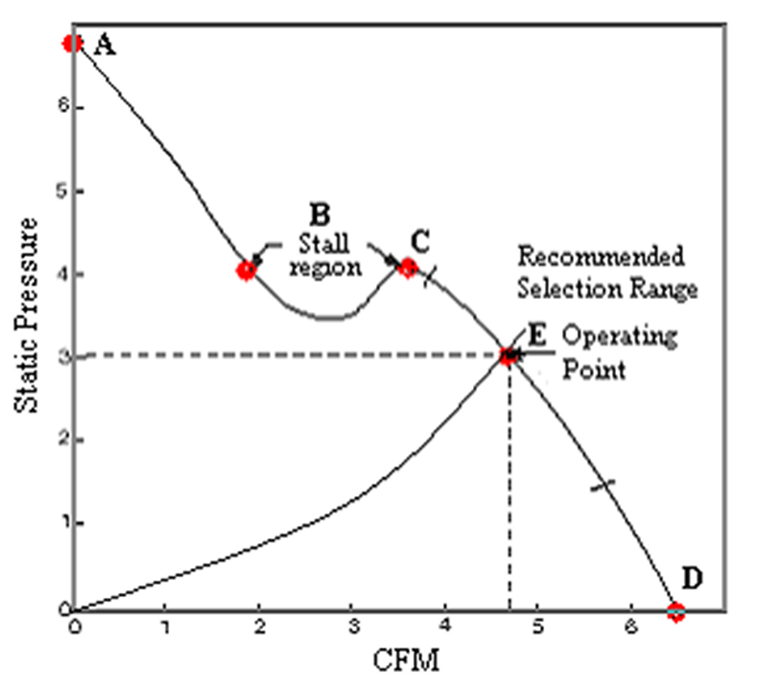
In the curve above:
- Point A represents the point of zero airflow. It is frequently referred to as “block off,” “shut off,” “no flow,” and “static no delivery.”
- Point B depicts the stall region of the static pressure curve. Operation in this area is discouraged because of erratic airflow that generates excessive noise and vibration.
- Point C depicts what is referred to as the peak of the static pressure curve, and
- Point D is the point of maximum airflow. Point D is also referred to as “free delivery,” “free air,” “wide open performance,” and “wide open volume.”
Curve segment CD is often referred to as the right side of the fan curve. This is the stable portion of the fan curve and is where the fan is selected to operate. It then follows that curve segment AC is the left side of the fan curve and is considered to be the unstable portion of the curve.
The fan static pressure curve is the basis for all airflow and pressure calculations. For a given SP on the static pressure curve, there is a corresponding CFM at a given rpm. Point E on the curve represents one such point on the fan curve. Simply locate some unit of pressure on the left hand SP scale and project a horizontal line to the point of intersection on the static pressure curve. From the point of intersection, project a vertical line to the bottom CFM scale to establish the corresponding airflow at that particular speed. In this example, a SP of three units results in a CFM of 4.71 units.
Note that point E is also known as the “operating point” (point of operation or design point), which corresponds to the condition at which the fan pressure rise (SP) / volumetric flow rate (CFM) characteristic intersects at operating or design condition.
Figure above is a vaneaxial curve with a pronounced dip (stall region) that is also a typical curve shape for high angle propeller fans and forward curve centrifugal fans. In contrast, compare this curve to figure below, which represents a typical curve for a backward inclined centrifugal fan. This curve shape is also representative of radial blade centrifugal fans.
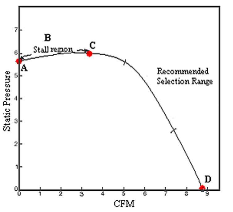
Note the lack of a pronounced dip on this curve. Nevertheless, the area left of peak is also a stall region and selections in this area should be avoided.
Related Posts:
Fan laws relate the performance characteristics of any geometrically similar series of fans. CFM, RPM, SP and HP are all related to each other in a known manner and when one changes, all others change…
Performance Characteristics of a Blower
The actual shape of blower performance curves is determined by the combined effect of the hydraulic losses of the impeller and casing. Mechanical losses including disk friction remains the same for all capacities and leakage loss is small and…